Rockfall Netting Installation: Step-by-Step Slope Stabilization Guide
On a slope protection job in the mountains two summers ago, our installation supervisor walked the site with the buyer's engineer before the netting went up. The engineer pointed at a long, weathered rock face and said, "this is the easy part - we just roll the mesh down the hill and pin it." Our supervisor looked up at the slope, then back at him, and said, "the mesh is the last thing that goes on. Today we walk the slope, mark the anchor positions, check the rope lengths, and decide which panels go where. If you want to roll the net tomorrow, fine, but the order matters more than the mesh does."
That conversation is the reason this guide exists. The mesh is what shows up on a quotation and what fills a photograph when the work is done. The installation - the actual work of putting a slope protection system into a real mountain - is what decides whether the system performs the next time a rock falls. This is a field-side walkthrough: what the system contains, how to pick the right one for your slope, the installation sequence crews actually follow, and the checks that catch the mistakes that get buried before anyone can see them again.
If you only have ten minutes, start here: the four system types in the next section, the three decision questions that pick the right one, and the four checks that have to happen before the anchor drill hits rock. The rest of the guide is the detail that makes those eight points reliable in the field.
Roadmap · 10 sections, in install order
- 01 What Is Rockfall Netting (and When You Actually Need It)
- 02 The Four Main System Types
- 03 How to Choose the Right System
- 04 Before You Start: Tools, Materials, Site Check
- 05 Step-by-Step: Active Drape Mesh
- 06 Step-by-Step: Passive Catch Fence
- 07 Common Mistakes We See in the Field
- 08 Quality Checks Before Handover
- 09 Maintenance & Inspection Schedule
- 10 FAQ: Installation Questions
Before you start
① The mesh never goes up before the anchors. Anchor first, mesh second, tensioning third - always in that order.
② The hardware list is longer than the mesh list. Posts, support ropes, brake rings, lacing and small parts typically make up 50-60% of the bill of materials on a passive barrier.
③ Document the anchors as you go. The highest-stress parts of the system are buried immediately after installation and cannot be inspected visually for the life of the barrier.
④ Match the system to the rock, not the budget. Picking a system one energy class below what the slope can deliver is the most common cost-saving that fails the day the slope actually fails.
1. What Is Rockfall Netting and When Do You Actually Need It?
Rockfall netting is the broad family of engineered mesh systems used to keep rock on a slope or catch it before it reaches a road, a rail line, or a structure. The mesh itself looks similar across the family, but the work it does varies widely - and that is where the first decision lies.
You typically need a slope protection system when one or more of the following applies to your site:
- The slope has loose blocks visible at the surface. If you can walk along the toe of a slope and pick up rocks the size of a football that obviously came from higher up, there is a rockfall problem whether anyone has called it that or not.
- The slope has been cut for a road, rail or building platform. Cut faces lose their natural root system and weathered skin, and newly exposed rock weathers faster than the undisturbed slope above. A cut face more than 4-5 m high in fractured rock is a candidate.
- There is a history of rockfall on the alignment. Even occasional rock on the road shoulder is a system trigger, not a "wait and see" situation - the next rock is rarely the same size as the last.
- The cost of one rockfall event is high. A road closure, a derailment, a damaged building or an injury all cost orders of magnitude more than a slope protection system installed in good conditions. Theconomic case usually makes itself.
What you do not need rockfall netting for: erosion control (use a coir mat or geomat), shallow soil sloughing (use a turf reinforcement mat), or rock slopes that are clearly stable with no jointing visible. Mesh on a stable face is a waste of money and a future maintenance liability.
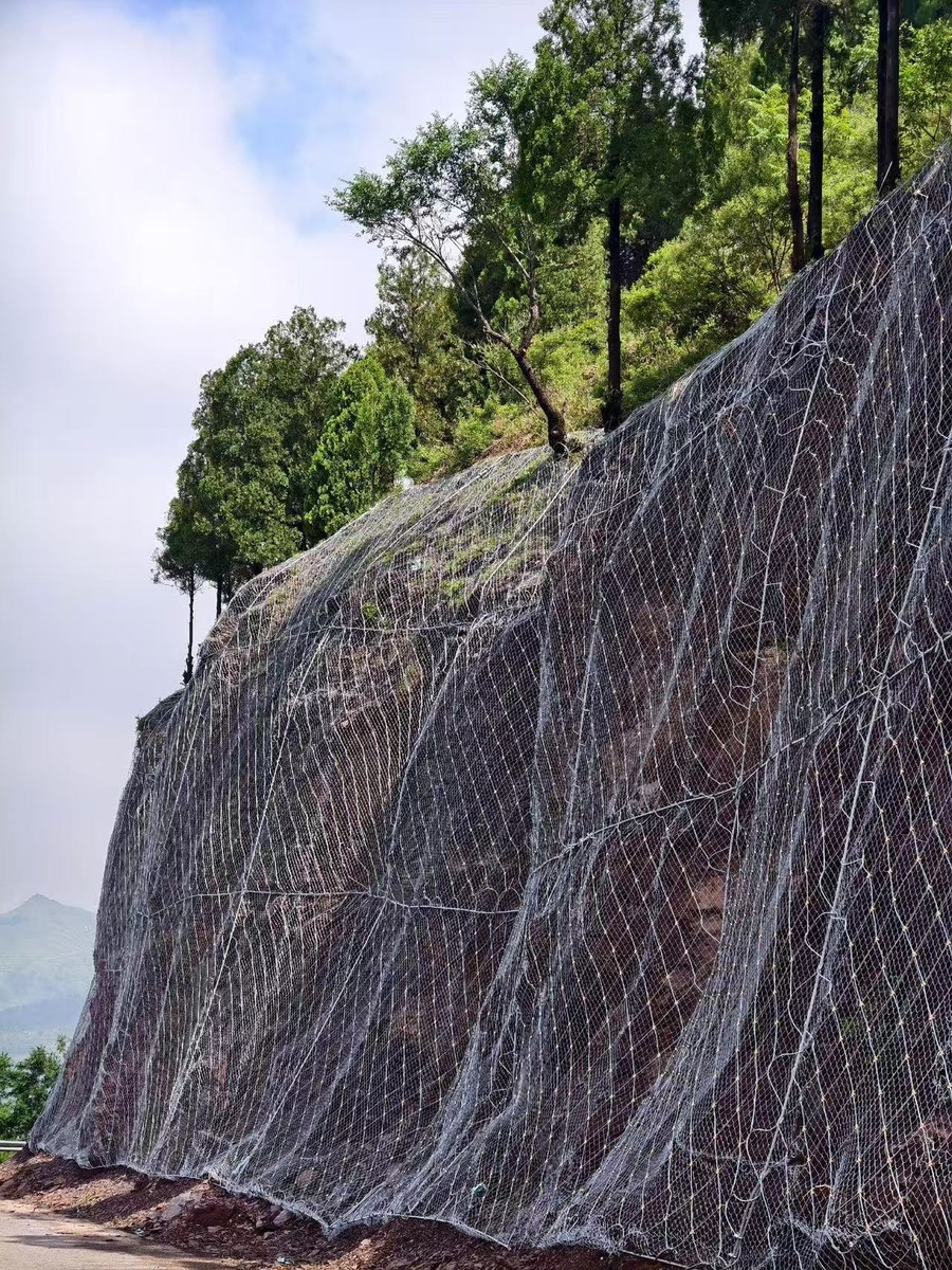
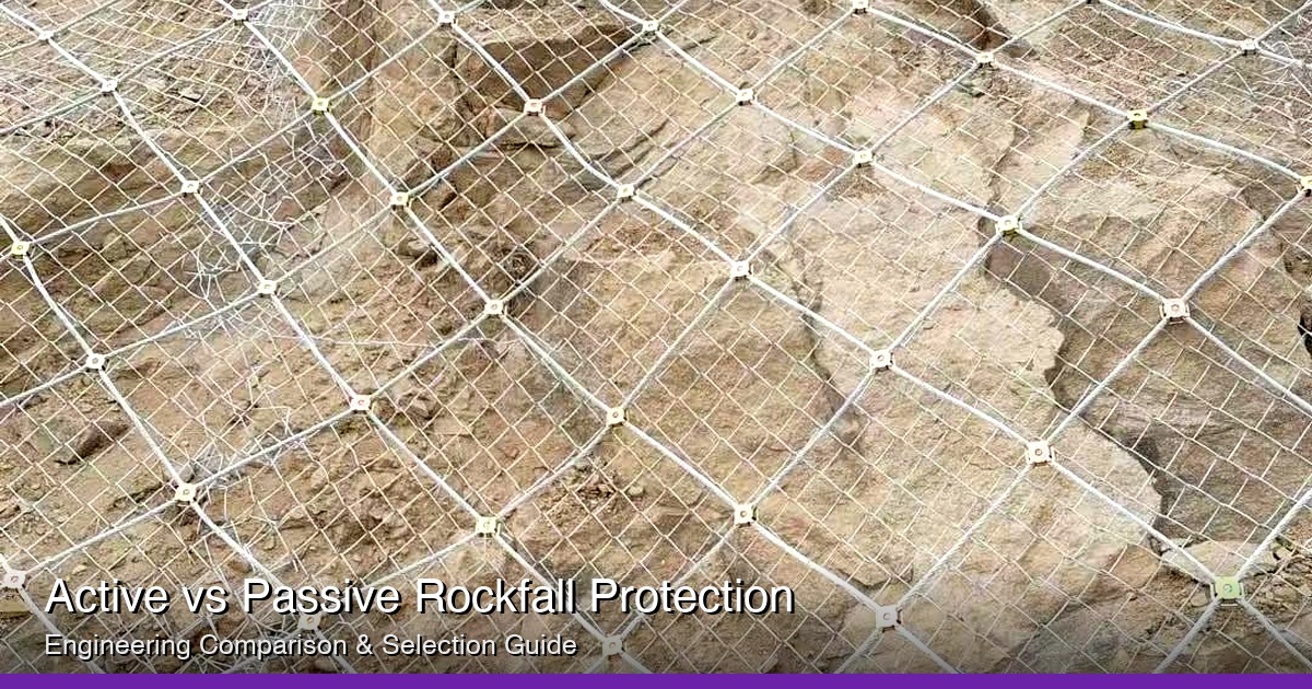
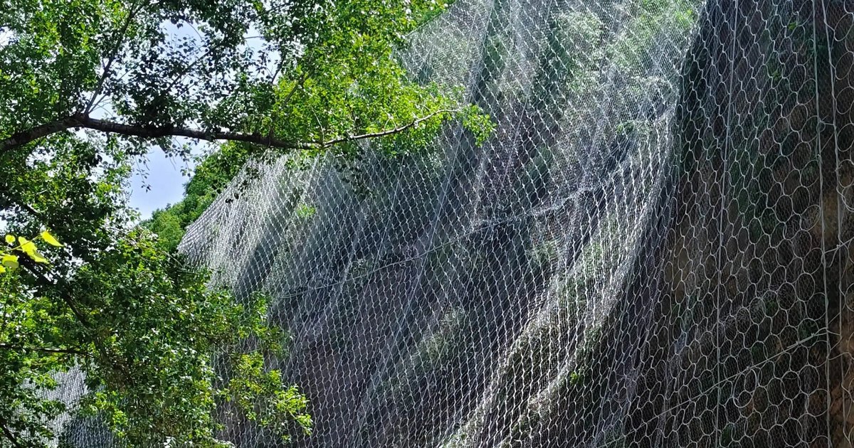
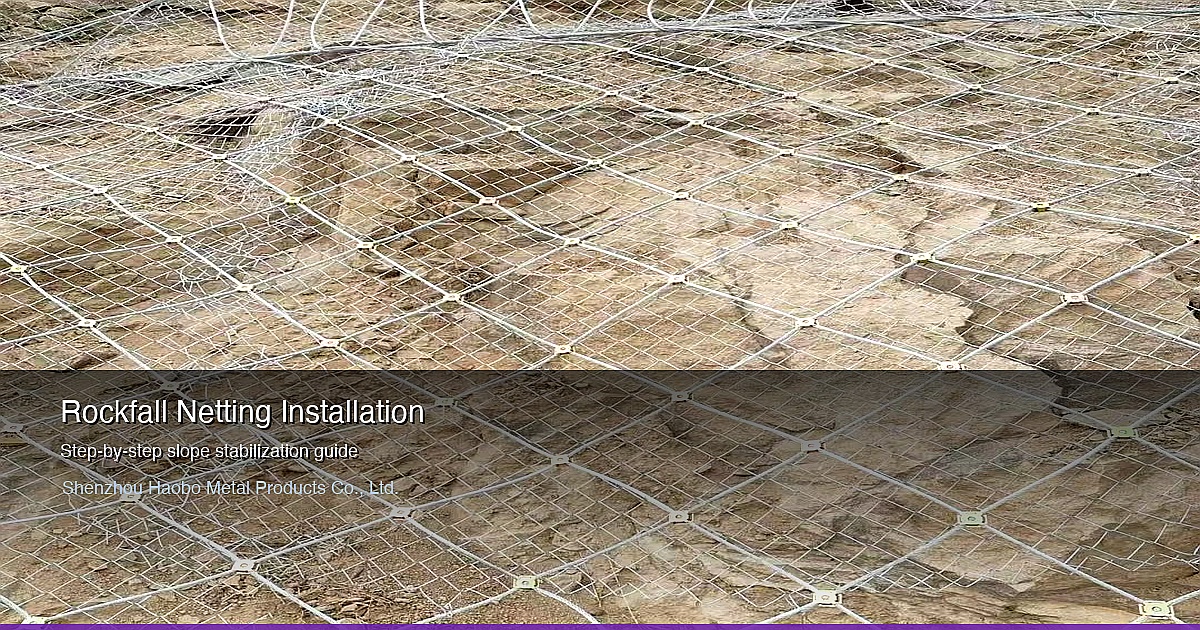
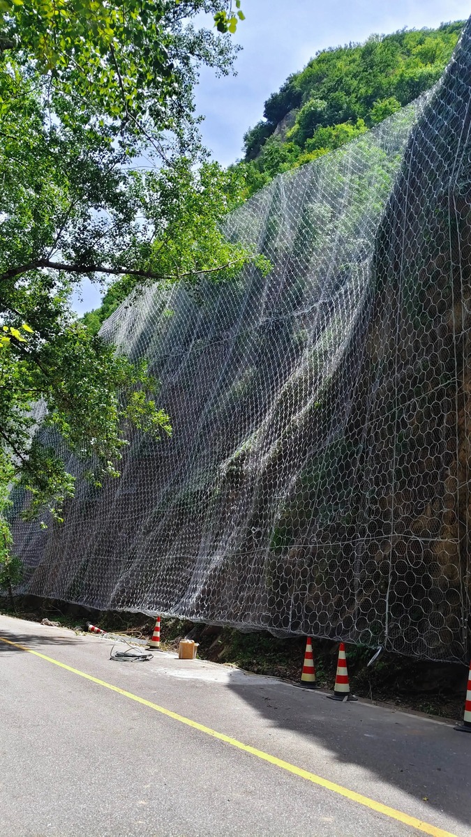
That photograph is from an active drape installation on a highway cut. The mesh is pinned to the slope face by anchors at the top and bottom, with edge rope running around the perimeter. Nothing in the picture is the structural anchor system - the anchors are short because the load path is into the rock face, not catching mid-air. That is the visual signature of an active system: the mesh conforms to the slope, the anchors are short and numerous, and there is no infrastructure downslope.
2. The Four Main Types of Rockfall Netting Systems
Within the family there are four distinct systems, each with its own hardware kit, installation sequence, and design energy level. The list below is in roughly increasing complexity, which is also the order in which cost and installation time rise.
2.1 Active Drape Mesh (the simplest)
Active drape mesh is a flexible mesh blanket pinned against the slope face to keep loose material from leaving the slope. The hardware list is short: mesh rolls, soil or rock anchors, edge rope, and the wire or clips that lace the panels together. The system works by containing the slope material rather than intercepting it mid-air, so the design energy is effectively zero - the mesh is not expected to catch a falling boulder, it is expected to keep cobble-sized and smaller material from rolling down the face.
Active drape is the right answer for fractured rock slopes where the failure mode is gradual loosening rather than discrete boulder release. It is the least expensive of the four systems, the fastest to install, and the easiest to maintain.
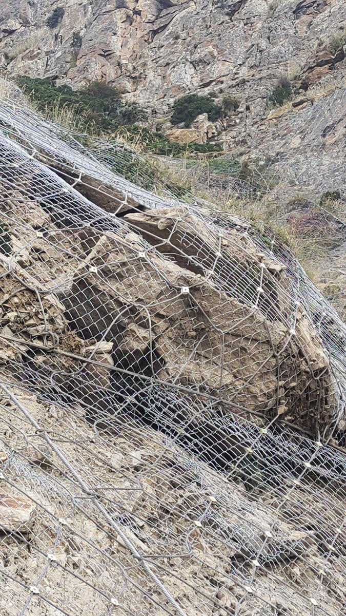
2.2 Active Anchored Mesh (with rock bolts)
Active anchored mesh looks similar to drape from the road, but the anchor pattern is denser and the anchors are longer rock bolts rather than short soil nails. The mesh still conforms to the slope, but the system is designed to hold larger blocks in place under higher load - blocks that a simple drape would let go after a few seasons of freeze-thaw.
This is the right answer for blocky rock slopes with discrete blocks that have visible jointing but no recent history of large boulder release. It is a step up in cost from drape, mostly because the rock bolts are more expensive to drill and grout than the short soil nails used for drape.
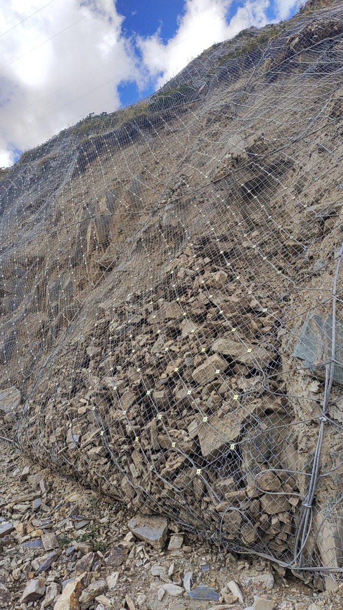
2.3 Passive Catch Fence (rockfall barrier)
Passive catch fences are the full SNS system most engineers picture when they say "rockfall barrier." The system stands downslope of the rock source, on its own posts and foundations, and intercepts rock in the air. The hardware list is the long one: posts, base plates, anchor bolts, support ropes, brake rings (energy dissipators), the wire rope or ring net panel itself, and the lacing and small parts that join the system.
Passive systems are specified by an energy class (typically ranging from 100 kJ to 8,000+ kJ depending on the test regime) that describes the kinetic energy the tested system has stopped in a standardized impact. That number is the single most important specification in the supplier's documentation - if the supplier cannot state the tested energy absorption of the model being offered, the rest of the quotation is a guess.
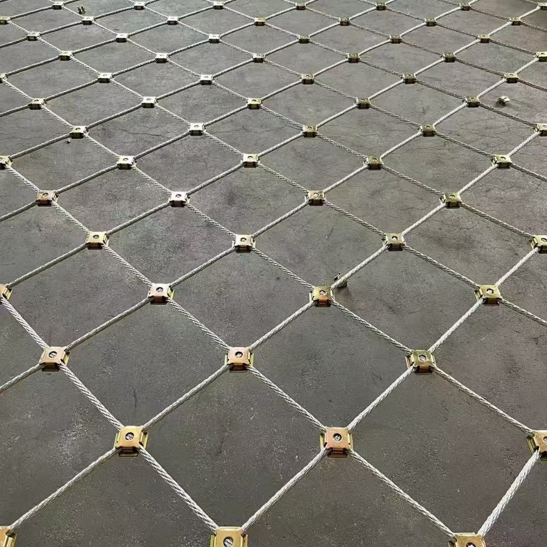
2.4 Hybrid Attenuator Systems
Hybrid systems combine an active mesh on the upper slope with a low-energy passive barrier at the toe. They are used where the upper slope needs containment but there is a high-consequence zone at the bottom - a road, a structure, a populated area - that warrants a second line of defense. Cost is high because you are building two systems, but the redundancy is what makes the hybrid the right answer on the most exposed alignments.
For a typical mountain highway cut in fractured rock, the most common pairing is anchored active mesh on the upper two-thirds of the face and a low-energy passive fence (typically in the 250-500 kJ class) at the ditch line. The mesh prevents the gradual release of small material that would otherwise fill the ditch; the fence catches the larger block that escapes the mesh during a storm or freeze-thaw event.
3. How to Choose the Right System for Your Slope
Choosing a slope protection system is a three-question decision tree. The answers are not budget questions - they are site questions, and getting them wrong costs more than any saving on the system.
Question 1: Where does the rock come from, and how does it move? If the failure mode is gradual loosening of surface material across a broad area, active drape or anchored mesh is the right answer. If the failure mode is discrete boulders detaching from a specific source zone and rolling or bouncing down a defined track, you need a passive fence in the path.
Question 2: What energy does the system need to absorb? For an active system, the energy is effectively zero - the mesh is not catching falling rock. For a passive system, the energy is determined by the boulder mass and the velocity at the barrier location, typically calculated using a rockfall trajectory model. The energy class of the barrier you specify has to exceed the calculated energy with a margin that the project engineer signs off on.
Question 3: What is downslope, and what is the consequence of a barrier breach? A barrier on a forest road above an unoccupied gully can be sized to a lower energy class than the same slope above a populated valley, because the consequence of a breach is different. This is the part of the decision where the engineer - not the supplier - has to make the call, and the engineer will document it.
The decision matrix below summarizes the typical selection by site condition. It is not a substitute for the project-specific design, but it is the right starting point for an inquiry.
| Site condition | Typical system | Energy class (if passive) | Anchor type | Indicative hardware complexity |
|---|---|---|---|---|
| Gradual surface loosening, no discrete boulders | Active drape | N/A | Short soil nails | Low (mesh + nails + edge rope) |
| Blocky rock with jointing, no recent large release | Active anchored mesh | N/A | Rock bolts (1.5-3 m) | Low to medium (mesh + bolts + edge rope) |
| Discrete boulder source, defined track | Passive catch fence | 100-500 kJ (low to mid) | Foundation + post anchor bolts | High (full SNS kit) |
| High-energy source, populated or critical downslope | Passive catch fence (higher class) | 500-2000+ kJ | Heavy foundations + post anchor bolts | High to very high (full SNS kit, larger section) |
| Combined gradual and discrete failure, high consequence | Hybrid (active + low-energy passive) | 250-500 kJ at the toe | Both systems, separate anchor designs | Very high (two systems) |
When NOT to use rockfall netting: on slopes where the failure mode is deep-seated (a wedge or planar slide involving a meter or more of rock mass) - those are slope stabilization problems requiring anchors, drainage, and possibly shotcrete, not mesh. On slopes where the source zone is above the practical reach of ropes and crews - the cost of accessing the anchor positions is itself a design constraint and may rule out mesh. And on slopes where the design requires removal of vegetation or soil to install anchors, where the environmental cost of the installation is unacceptable - mesh is not a substitute for the slope's natural root system.
4. Before You Start: Tools, Materials, Site Check
The first day on a slope protection job is not a drilling day. It is a walk-around, mark-up, and paperwork day. The objective is to make sure the materials on the truck match the slope, the anchor positions are marked and agreed, and the documentation system is in place before any hole is drilled.
4.1 Materials You Will Have on Site
- Wire rope or ring net panels in the mesh type and roll dimensions specified on the design drawing
- Support ropes (upper and lower) for passive systems, sized to the span and energy class
- Posts and base plates for passive systems, hot-dip galvanized, with anchor bolts matched to the foundation design
- Brake rings (energy dissipators) for passive systems, in the quantity and orientation specified on the drawing
- Anchor rods - soil nails for drape, rock bolts for anchored mesh, foundation bolts for passive posts - in the lengths and grades on the drawing
- Edge rope, lacing rope, shackles, clips - the small parts kit, supplied with modest overage
- Grout or resin cartridges for the anchor installation, matched to the anchor supplier's documentation
4.2 Tools the Crew Brings
Rock drill (handheld for small jobs, excavator-mounted for larger ones), grout mixer, caliper for wire and rope diameter checks, magnetic zinc-coating gauge, tensioning equipment (come-along or hydraulic jack) sized to the rope spec, torque wrench for post anchor bolts, and a pulley system for lifting panels to the anchor positions on steep faces. Safety gear for working at height is not optional on any slope where the anchor pattern is above head height.
4.3 Site Check Before the First Drill
Three things to walk and document on day one:
- Match the drawing to the ground. The design drawing assumes a certain slope geometry, anchor spacing, and source zone. If the ground does not match the drawing - a hidden overhang, an unexpected seepage line, a different rock type at the actual anchor positions - the engineer has to revise the design before the crew drills, not after.
- Identify access routes for materials. Netting rolls, posts and rope coils are heavy. A 200 m roll of wire rope mesh does not move itself up a 50 m slope. Plan where the truck parks, where the staging area is, and how the materials get to the anchor line before the truck arrives, not after.
- Confirm the documentation system. The anchor log template, the heat number tracking, the daily progress photo set - all of this needs to be agreed and started before the first drill hole, because once the crew is working, the paperwork falls behind quickly.
5. Step-by-Step: Active Drape Mesh Installation
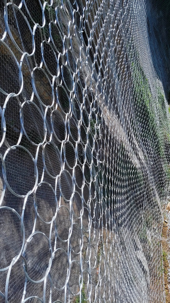
Active drape is the simplest of the four systems and the right place to start the walkthrough. The sequence below is what a well-run crew follows in good conditions; actual timing varies with slope height, access and crew size.
5.1 Step 1 - Clear the Slope Face
Remove loose blocks, vegetation that would interfere with mesh contact, and any debris from the drilling access. This is the step that gets cut when a crew is behind schedule, and it is the step that determines whether the mesh can actually drape the slope without spanning voids. Loose cobbles under the mesh become point loads on the lower edge of the panel, which becomes a tear point in the second winter.
5.2 Step 2 - Mark the Anchor Pattern
Mark the top anchor line, the bottom anchor line, and the intermediate anchor rows per the design drawing. On a typical 4 m spaced anchor pattern, this is a string line and paint, run from the crest to the toe. The anchor positions have to match the mesh roll width plus an overlap that the design specifies - mismatches here mean a panel has to be cut on site, which is the beginning of a fitting problem.
5.3 Step 3 - Drill the Anchor Holes
Drill to the depth on the drawing, with the hole diameter matched to the anchor and grout specification. Record the actual drilled depth, the ground condition encountered (solid rock, fractured rock, soil, voids), and any deviation from the design on the anchor log. This is the data that backs the as-built documentation - if it is not recorded now, it does not exist later.
5.4 Step 4 - Install the Anchors
Insert the anchor rod, set it to the design depth, and grout or resin-fix per the supplier's procedure. Allow the grout to cure to the specified strength before loading the anchor - the temptation to load anchors early to keep the crew working is the second most common shortcut on a slope job, and it is the one that produces failed anchors under the first impact load.
5.5 Step 5 - Hang the Edge Rope and Mesh Panels
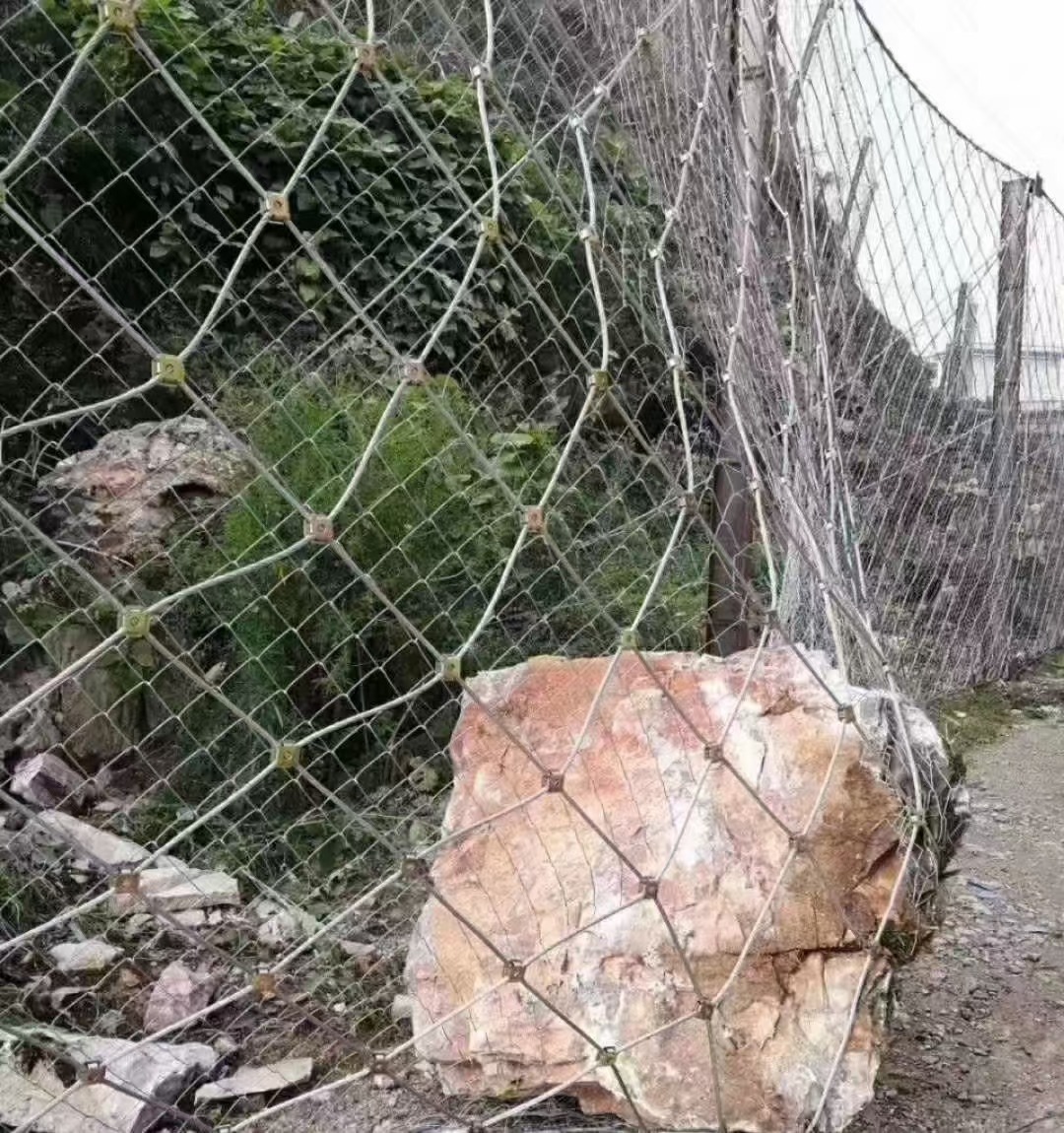
Thread the edge rope through the top anchor line and tension to the design sag, then unroll the mesh panels from the top down, lacing adjacent panels together with the specified connecting rope. The lacing is where crews substitute lighter wire than specified - the proper lacing rope is stiffer and slower to work with, but it is sized to the system. Mismatched lacing is the most common cause of panel separation under impact.
5.6 Step 6 - Tension and Final Anchor Check
Tension the bottom edge rope to bring the mesh into contact with the slope, then walk the system checking that every anchor is seated and every panel is laced. The mesh does not need to be drum-tight - the design intent is contact with the slope, not a trampoline surface.
6. Step-by-Step: Passive Catch Fence Installation
Passive barriers are the long-hardware-list systems. The installation sequence has more steps, more parties involved (the foundation crew, the post crew, the rope and net crew), and more places where shortcuts cost the project.
6.1 Step 1 - Survey and Set Out the Post and Foundation Positions
Mark each post position and each anchor bolt location to the design tolerances. On a typical passive barrier, the post spacing is 6-10 m depending on the energy class - the higher the class, the closer the posts. Foundation type (concrete pad, micropile, rock anchor) depends on the ground conditions at each post and the energy class of the system.
6.2 Step 2 - Construct the Foundations
Excavate, form, reinforce, and pour or drill and grout the foundations per the design. Allow the foundation to cure to the specified strength before erecting the posts - the most common cause of a barrier failing on first impact is a foundation that was loaded before it had reached the strength the design assumed.
6.3 Step 3 - Erect the Posts
Set each post on its base plate, shim to the design vertical alignment, and tension the anchor bolts to the specified torque. The posts are the visible frame of the barrier and the easiest thing to check from a passing vehicle, which is why foundation work - which is not visible - is where the quality control attention needs to be.
6.4 Step 4 - Install the Support Ropes and Brake Rings
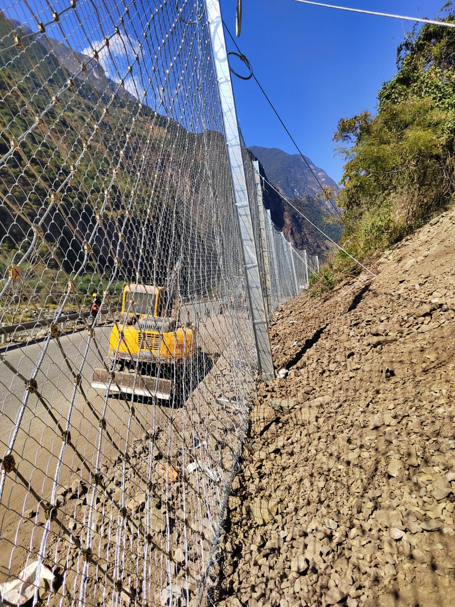
Span the upper and lower support ropes between posts, install the brake rings at the rope-post junctions, and bring the ropes to the design tension. The brake rings are the energy dissipators and they work by deforming - a brake ring that has already deformed in handling or storage is partially spent before the barrier is even handed over. Check the rings at receiving and again before installation.
6.5 Step 5 - Hang the Net Panels
Unroll or lift the net panels (ring net, wire rope net, or hybrid) into the support rope span, lace the panels together at the edges, and connect to the support ropes with the specified shackles. The lifting is the most physically demanding step on a passive barrier - panel weights of 50-150 kg per section are typical, and they have to be lifted to the upper support rope height.
6.6 Step 6 - Tension and Brake Ring Setup
Tension the system in the sequence specified by the manufacturer (typically symmetrically from the middle of a span outward), check that the brake rings are correctly oriented, and confirm the design height is achieved along the barrier. A barrier that has been tensioned in the wrong order never reaches design tautness no matter how much the end fittings are tightened afterwards.
6.7 Step 7 - Handover Inspection and Documentation
Final walk with the engineer, the anchor log, the mill certificates, the brake ring inspection record, and the as-built drawing. The handover inspection is the last point at which a deficiency is the supplier's problem rather than the owner's; after that, the system belongs to the maintenance schedule.
7. Common Mistakes We See in the Field
These are the issues our installation supervisor sees on a majority of jobs that are not his own crew. None of them are exotic - they are the boring, easily-avoided mistakes that show up because the day is long and the slope is steep.
1. Anchors loaded before grout cure. The grout or resin has a specified cure time, and the anchor has a specified strength at the time of loading. Loading an anchor early to keep the crew working produces an anchor that tests fine on the day of installation and fails under the first significant load event - usually a few years later, in a storm, when the anchor is no longer accessible to inspect or replace.
2. Sub-gauge wire or rope substituted for the specified lacing. The lacing rope is sized to the system and is the joint that takes the load between panels and between the net and the support rope. A lighter wire works for the day of installation and fails under the first impact load or the first winter's freeze-thaw. The check is a caliper, against the specification sheet in the crate.
3. Brake rings installed in the wrong orientation. The brake ring is an energy dissipator that deforms in a specific direction under load. Installed backwards, it does not deform as designed, and the energy that should have been absorbed by the ring is transferred directly to the support rope and the post anchor. The check is visual, against the drawing.
4. Net panels installed with the wrong overlap. Adjacent panels are either laced edge-to-edge or overlapped by at least a full mesh aperture, per the design. Overlap that is too small produces a gap wide enough for the design rock size to pass; overlap that is too large wastes material and adds weight the system was not designed for. The check is a tape measure on the seam.
5. Documentation deferred to the end of the job. The anchor log, the heat number tracking, the daily progress photos - none of these can be reconstructed at the end of the job from memory. The system goes in over weeks, the documentation is done daily or it is not done at all. The single most effective project management tool on a slope protection job is the discipline of paperwork at the end of each day.
8. Quality Checks Before Handover
The handover inspection is the last point at which the supplier's quality control is verifiable on site. These are the checks that should be in the inspection record, in the order they are typically performed.
| Check | What is verified | Reference |
|---|---|---|
| Anchor log completeness | Every anchor has depth, ground condition, grout batch, and pull-out test result (where specified) | Project specification / design drawing |
| Mill certificates match heat numbers on the goods | Wire rope, mesh, posts and fittings all traceable to the supplied documents | JT/T 528-2022 (where applicable) |
| Wire and rope diameter by caliper | Sampled per coil and per bundle, straight runs recorded | Specification sheet in the crate |
| Zinc coating weight by magnetic gauge | Sampled wire and rope; hot-dip floor 245 g/m² for slope protection mesh and ropes | GB/T 1839 test methods |
| Brake ring condition | No deformation in handling or storage; correct orientation at installation | Design drawing / manufacturer installation manual |
| Fitting grades and markings | Shackles and clips rated and stamped; no unmarked generic hardware | Specification sheet in the crate |
| Post coating on cut edges | Fabrication cuts and field-cut posts re-protected with zinc-rich paint | Project specification |
None of this requires laboratory equipment - a caliper, a coating gauge, the system drawing and a couple of hours. The expensive version of this checklist is the one performed after a failure, written by whoever the insurance company appoints.
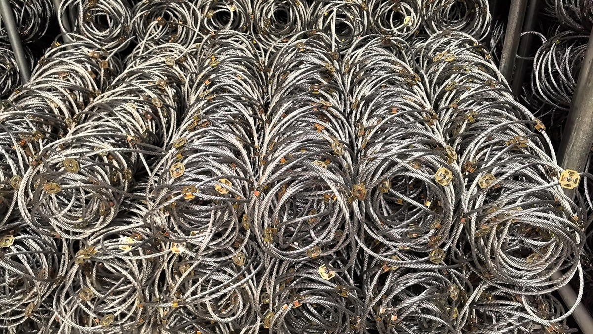
9. Maintenance & Inspection Schedule
A slope protection system is not a "fit and forget" installation. The mesh, ropes and anchors all degrade; the slope above the system continues to weather; vegetation grows through the mesh and adds load it was not designed for. A simple annual inspection catches most of these issues before they become failures.
9.1 Annual Visual Inspection
Walk the system once a year, ideally after the wet season or spring snowmelt. Look for: torn mesh, slack support ropes, deformed brake rings, vegetation overgrowth, anchor plate exposure (where the soil or grout has eroded around a base plate), and any new rockfall debris caught by the system that has not been cleared. Document any change from the previous year with a photograph - the trend matters more than the snapshot.
9.2 Five-Year Detailed Inspection
Every five years, a closer inspection: zinc coating thickness on the visible mesh and ropes (the design assumes a corrosion rate, and the actual rate varies with site conditions), torque check on the post anchor bolts, and a sample check of the foundation grout above the base plate. The five-year inspection is also the time to plan any major refurbishment, which is far cheaper to budget than to emergency-procure.
9.3 Post-Event Inspection
After any significant rockfall event that the system has actually caught, an immediate inspection: number and size of blocks caught, condition of the net and ropes, any deformation of posts or brake rings, and any damage to the foundations. A system that has done its job once has done a significant amount of work and may need partial refurbishment before it is fully rated for the next event.
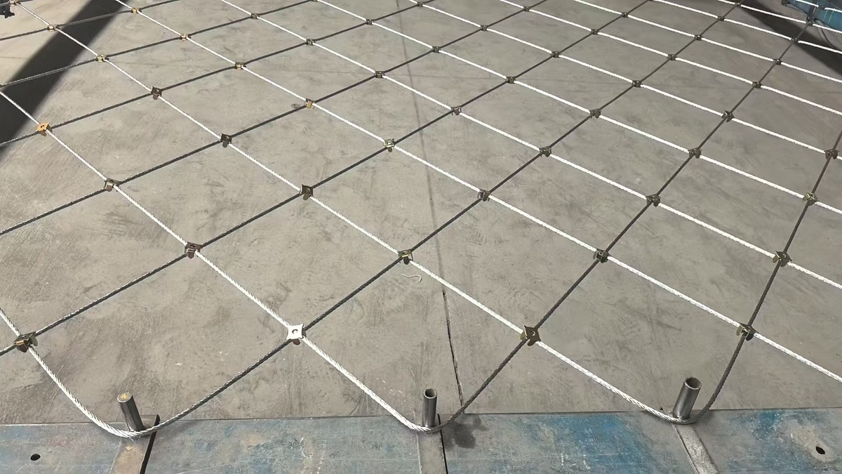
10. FAQ: Rockfall Netting Installation Questions
The questions below are the ones our installation supervisor hears most often from buyers before their first slope protection order.
How do I decide between active mesh and a passive barrier for my slope?
The short version: if the failure mode is gradual loosening of small material, active mesh. If the failure mode is discrete boulders detaching from a defined source and rolling down a track, a passive barrier. If both, consider a hybrid. The project engineer should run a rockfall trajectory analysis to confirm the energy class of any passive system - the design energy is not a guess and not a single number that applies to all sites.
What is the difference between drape mesh and anchored mesh?
Both are active systems where the mesh conforms to the slope face. Drape mesh uses short soil nails and holds the slope material in place; it is for gradual loosening with no large boulders. Anchored mesh uses longer rock bolts at a denser pattern and is for blocky rock with visible jointing. The mesh types look similar from the road, but the hardware list and design energy are different, and the cost difference is mostly in the anchor drilling and grouting.
What is an "energy class" on a passive rockfall barrier?
Energy class is the kinetic energy, in kilojoules, that a tested barrier system has been demonstrated to stop in a standardized impact test. The test regime varies by region and standard (European ETAG 027, Swiss FOEN, and others define test methods differently), so a model name from one supplier is not directly comparable to another without knowing the test behind it. Always ask the supplier to state the tested energy absorption behind the model code, not just the class number.
Can a slope protection system be installed in winter?
It can, but with constraints. Grout and resin cure times are temperature-dependent and most anchor systems specify a minimum installation temperature; frozen ground changes the drilling and the anchor behavior in soil slopes. Cold-weather installation is feasible on rock slopes with appropriate products, but it adds cost and requires a more experienced crew. Most projects in cold climates schedule the installation for the shoulder seasons (autumn or spring) when ground conditions are workable but the freeze-thaw cycle that drives rockfall has not yet started.
How long does a properly installed slope protection system last?
Design life for a hot-dip galvanized slope protection system is typically 25-50 years depending on the corrosion environment (coastal, industrial, or normal rural atmosphere) and the coating class specified. The mesh, ropes and posts are designed to that life; the small parts (shackles, clips) and the brake rings are typically the first items to need replacement, and the five-year inspection is the right point to plan for those. An active system in a low-corrosion environment can last longer; a passive system in a coastal or industrial environment can need major refurbishment earlier.
What is the most common reason a slope protection project is delayed?
Accessories. The mesh is the visible part of the order and the easiest thing to procure; the posts, ropes, brake rings, anchors and small parts are procured separately and frequently arrive on a different schedule from a different vendor. By the time the crew is on site with the mesh, the hardware is still in a container, and the project waits. Specifying and procuring the complete system as a single package, packed by sub-system with a drawing-mapped packing list, removes this failure mode.
What standards apply to slope protection nets manufactured in China?
Highway and similar slope protection nets are governed by JT/T 528-2022, the transportation-industry standard. Material lines to expect on mill certificates include steel wire rope with tensile strength of at least 1770 MPa and hot-dip zinc coating of at least 245 g/m², with coating weight verified per GB/T 1839 test methods. For projects outside China, the local design standard (ETAG 027 in the EU, equivalent national standards elsewhere) defines the energy class and the test regime; the material standards in JT/T 528-2022 are typically compatible.
Send the site, get the complete system
Send us the slope country, the approximate barrier length and height, and your destination port. We quote the complete package - active mesh, or passive barrier with mesh, posts, support ropes, brake rings, anchors and small parts - as named line items with mill certificates tied to heat numbers, and packing mapped to the system drawing. Materials to JT/T 528-2022, FOB Tianjin.
Shenzhou Haobo Metal Products Co., Ltd. · slope protection systems to JT/T 528-2022 · www.haobomesh.com
Continue with these