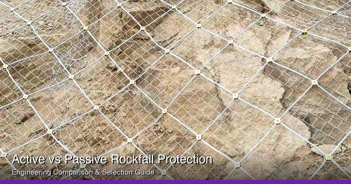
Rockfall Netting Installation Guide: Step-by-Step for Slope Protection
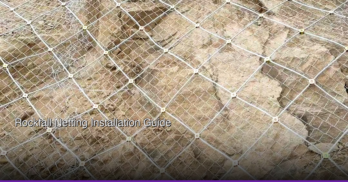
Rockfall netting installation is a critical engineering process that protects infrastructure, transportation corridors, and communities from the devastating impact of rockfall events. When properly designed and installed, rockfall protection systems can intercept, contain, or prevent rock displacement with reliability rates exceeding 95%. However, improper installation can lead to catastrophic failure, property damage, and loss of life. This comprehensive guide walks through every step of the rockfall netting installation process, from initial site assessment through final inspection, covering both active and passive protection systems in accordance with ETAG 027 (European Technical Assessment Guideline) and Eurocode 7 (EN 1997) standards.
Key Takeaways
- Site assessment first: Geological survey determines the entire system design — never skip this step
- ETAG 027 compliance: All components must meet European Technical Assessment standards for rockfall protection systems
- Anchor depth matters: 2-6m embedment depending on rock quality, always verified by pull-out testing
- Top-down deployment: Mesh panels unroll from crest to toe for safety and proper overlap
- Annual inspection mandatory: Post-storm checks catch damage before failure occurs
📌 Table of Contents
1. Site Assessment and Risk Analysis
Before any material is ordered or equipment mobilized, a thorough site assessment must be conducted. This is not a formality — it is the foundation upon which the entire protection system is designed. A poorly assessed site leads to under-engineered protection that fails when it matters most.
The assessment process involves multiple disciplines working together:
- Geological survey: Identify rock types (igneous, sedimentary, metamorphic), weathering grades, fracture patterns, joint sets, and fault zones. Rock mass classification using the Q-system or RMR (Rock Mass Rating) provides quantitative basis for design.
- Topographic survey: Document slope geometry including height, angle, and profile variations. Digital terrain models (DTM) from drone surveys or LiDAR provide millimeter-accurate surface data.
- Rockfall trajectory analysis: Using software like RocFall or CRSP, simulate potential rockfall paths to determine bounce heights, kinetic energy, and runout distances. This determines whether active or passive systems are appropriate.
- Drainage assessment: Water is the primary trigger for rockfall. Identify groundwater seepage points, surface runoff channels, and freeze-thaw cycles that accelerate rock weathering.
- Access evaluation: Determine how equipment and materials will reach the installation site. Steep, remote slopes may require helicopter transport or specialized rope-access techniques.
The output of the site assessment is a formal Rockfall Hazard Assessment report that includes:
| Assessment Parameter | Method | Design Input |
|---|---|---|
| Rock mass quality (Q/RMR) | Core logging + scanline survey | Anchor capacity, mesh type |
| Slope geometry | Drone photogrammetry / LiDAR | System layout, coverage area |
| Rockfall energy | RocFall / CRSP simulation | Energy class (250kJ - 3000kJ) |
| Bounce height | Trajectory analysis | Fence height, mesh coverage |
| Design block size | Stereonet + block survey | Mesh aperture, rope spacing |
2. Material Selection and System Components
Rockfall protection systems are categorized into two fundamental types, each serving different engineering purposes. Selecting the wrong type for your site conditions is a critical and costly error.
Active Protection Systems
Active systems are anchored directly to the rock face, holding potentially unstable material in place. They are used when the rock mass is fractured but generally stable — the mesh prevents individual blocks from detaching and accelerating down the slope.
Key components of an active system include:
- High-tensile steel wire mesh: Typically TECCO mesh (3mm wire, 80mm aperture) or similar high-tensile mesh with breaking strength ≥250 kN/m. The mesh must accommodate the design block size while preventing smaller fragments from passing through.
- Anchor bolts: Grouted threadbar anchors, typically Ø25-32mm, with yield strength ≥500 MPa. Embedment depth varies from 2m (sound rock) to 6m (fractured rock). Each anchor must be tested to verify pull-out capacity meets design loads.
- Spike plates: Steel bearing plates (200×200×8mm typical) that distribute anchor load across the mesh. Curved plates conform to irregular rock surfaces.
- Perimeter ropes: Wire rope (Ø12-22mm) installed along the top, bottom, and sides of the mesh panel to distribute loads and provide edge anchoring.
- Stitching wire: Used to connect adjacent mesh panels. Must match or exceed the tensile strength of the mesh wire.
Passive Protection Systems
Passive systems intercept falling rocks at the slope toe or at intermediate points on the slope. They include ring-net barriers, attenuators, and draped mesh systems. These are used when active stabilization is impractical or when the risk of large-scale slope failure is low but individual rockfall events are frequent.
| System Type | Energy Rating | Typical Height | Best Application |
|---|---|---|---|
| Draped mesh (simple) | Low energy (< 100kJ) | Full slope coverage | Raveling, small fragments |
| Ring net barrier (R1-R3) | 250 - 500 kJ | 3 - 5 meters | Highway, railway protection |
| Ring net barrier (R4-R5) | 1000 - 2000 kJ | 4 - 7 meters | Mining, large infrastructure |
| Attenuator system | 500 - 3000 kJ | 6 - 12 meters | Ditch-constrained corridors |
Corrosion Protection
All steel components must have corrosion protection appropriate for the site environment. Standard options include:
- Hot-dip galvanized: Minimum coating mass 245 g/m² (Class A). Suitable for most rural and alpine environments with atmospheric corrosivity category C1-C3.
- Galfan (Zn-5%Al):strong> Superior corrosion resistance, 3x longer service life than standard galvanizing. Required for marine environments (C4-C5) and when design life exceeds 50 years.
- PVC coating: Applied over galvanized wire for highly corrosive environments. Adds UV stability and aesthetic options. Total coating thickness ≥0.5mm.
3. Anchor Bolt Installation
Anchor bolts are the backbone of any active rockfall protection system. Their capacity directly determines the system's ability to hold rock in place. Installation must follow strict procedures to ensure each anchor achieves its design pull-out capacity.
Drilling Procedure
Anchor holes are drilled using rotary percussive drills, either hand-held (for accessible sites) or mounted on specialized platforms. Key requirements:
- Hole diameter: Typically 50-90mm, depending on bolt diameter and grout cover requirements
- Hole depth: Design embedment + 100mm tolerance for grout injection tube
- Hole orientation: Within ±5 degrees of design angle (usually normal to rock surface)
- Hole cleaning: Blow out drill cuttings with compressed air before bolt insertion
Grouting Procedure
Cement grout provides the bond between the bolt and the surrounding rock. Proper grouting is essential for achieving design capacity:
- Grout mix: Water-cement ratio of 0.4-0.45 using Type I Portland cement. Minimum compressive strength 30 MPa at 28 days.
- Injection method: Tremie method — grout injected from the bottom of the hole upward through a PVC injection tube. This prevents air entrapment and ensures complete fill.
- Curing time: Minimum 7 days before applying any load. Full design capacity at 28 days.
- Temperature control: Do not grout when ambient temperature is below 5°C or above 35°C without appropriate measures.
Anchor Testing
Every anchor must be proof-tested before the mesh is connected. Testing protocols per ASTM D4435 or equivalent:
| Test Type | Load Applied | Acceptance Criteria |
|---|---|---|
| Proof test (every anchor) | 1.2 × Design Load | Displacement < 2mm at sustained load |
| Verification test (5% of anchors) | 1.5 × Design Load | Creep < 1mm over 10 min |
| Creep test (2% of anchors) | 1.2 × Design Load | Creep rate < 2mm/log cycle |
Any anchor failing the proof test must be replaced or supplemented with additional anchors. Document all test results in the as-built report.
4. Mesh Panel Deployment and Securing
Mesh deployment is a methodical process that begins at the top (crest) of the slope and proceeds downward. This top-down approach serves both safety and engineering purposes — workers are never positioned below unsecured mesh, and gravity assists in the deployment.
Preparation
- Unroll mesh panels at the crest, aligning them with the designed panel layout
- Verify panel dimensions match the site layout drawing (typical panel width: 3-4m)
- Install the top perimeter rope first, securing it to crest anchors at designed spacing
- Attach lifting ropes to the top edge of each mesh panel for controlled lowering
Deployment Sequence
- Attach top edge: Connect the mesh top edge to the perimeter rope using stitching wire or rope clips at 200mm intervals
- Lower mesh panel: Using ropes and winches, slowly lower the mesh down the slope face. Workers positioned on ropes guide the mesh to ensure it follows the rock surface contour
- Sideways overlap: Adjacent panels must overlap by a minimum of 100mm (one mesh aperture). Connect overlap edges with stitching wire at 150mm intervals
- Intermediate anchoring: At designed grid points (typically 2-3m spacing), install spike plates through the mesh into pre-drilled anchor bolts
- Bottom perimeter: Connect the mesh bottom edge to the toe perimeter rope or toe anchor chain
Critical Quality Points
- Mesh must be in full contact with the rock surface — bridging or gaps indicate insufficient tension
- Stitching wire connections must be tight — loose connections will unravel under load
- Spike plates must bear flat against the mesh — bent or tilted plates concentrate stress and can tear the mesh
- All connections must use wire of the same or higher tensile class as the mesh
5. Tensioning and Final Securing
Proper tensioning transforms a loosely draped mesh into an engineered restraint system. Without adequate tension, the mesh will sag, allowing rock blocks to mobilize and potentially break through. The tensioning process must be systematic and verified.
Tensioning Procedure
- Top-down sequence: Begin tensioning from the crest anchors, working downward in rows
- Apply tension: Use come-along winches or hydraulic tensioners attached to the spike plate bolts. Apply tension gradually (25% increments) to avoid shock loading
- Verify tension: The mesh should be taut against the rock surface with no visible sag between anchor points. A deflection test — pressing the mesh by hand — should show minimal movement (< 20mm)
- Torque bolts: Once tension is achieved, torque the spike plate nuts to the manufacturer's specified value (typically 80-120 Nm for M24 bolts)
- Secure connections: Double-check all perimeter rope connections, stitching wire ties, and overlap connections
Perimeter Rope Tensioning
Perimeter ropes distribute loads between anchors and provide a continuous load path around the mesh panel. Tension perimeter ropes to the design value using a rope tensioner:
| Rope Diameter | Min. Breaking Load | Design Tension | Application |
|---|---|---|---|
| 12mm | 84 kN | 15-20 kN | Top/bottom perimeter |
| 16mm | 149 kN | 25-30 kN | Lateral perimeter |
| 22mm | 280 kN | 40-50 kN | High-energy systems |
6. Post-Installation Inspection and Maintenance
Installation is not complete until a thorough inspection has been conducted and a maintenance plan is established. Rockfall protection systems are subjected to continuous environmental loading — thermal cycling, freeze-thaw, seismic activity, and vegetation growth all affect long-term performance.
Final Inspection Checklist
- ☐ All anchor bolts torqued to specification and marked with torque verification paint
- ☐ Mesh is in full contact with rock surface — no sagging, bridging, or gaps
- ☐ All spike plates are flat against mesh and properly torqued
- ☐ Perimeter ropes are tensioned to design values with rope tension meter
- ☐ All stitching wire connections are tight and show no signs of loosening
- ☐ Mesh overlap joints are properly connected at correct spacing
- ☐ No damaged mesh wires or broken strands
- ☐ Drainage provisions behind mesh are functioning (no water ponding)
- ☐ As-built drawings updated with any field modifications
- ☐ Photo documentation of completed installation
Annual Maintenance Protocol
| Inspection Item | Frequency | Action Required |
|---|---|---|
| Visual mesh inspection | Annual | Repair tears, replace damaged panels |
| Anchor bolt torque | Every 2 years | Re-torque to specification |
| Debris removal | Post-event + annual | Remove accumulated rock, soil, vegetation |
| Corrosion assessment | Every 5 years | Measure coating thickness, assess service life |
| Post-storm inspection | After major events | Full inspection within 48 hours |
Documentation Requirements
Maintain a complete installation and maintenance record including:
- Original design calculations and drawings
- Anchor pull-out test reports
- Material certificates (wire mesh, ropes, anchors, grout)
- As-built drawings with field modifications
- Photo documentation (pre-installation, during installation, post-installation)
- Inspection logs and maintenance records
- Repair history with dates and descriptions
Proper documentation is not just paperwork — it is legal protection, engineering reference, and maintenance planning tool. In the event of a rockfall incident, complete documentation demonstrates that the system was designed and installed to recognized standards.
For projects requiring professional installation supervision, Haobo Metal provides on-site technical support including design verification, installation training, and quality inspection services. Our engineering team has supervised rockfall protection installations across 50+ projects in Europe, South America, and Southeast Asia, ensuring compliance with ETAG 027 and local standards.
Need Rockfall Protection for Your Project?
Get factory-direct pricing on ETAG 027 certified rockfall netting systems. Free design consultation and installation guidance available.