Rockfall Protection Design Guide: Energy Ratings, System Selection & Cost Estimation
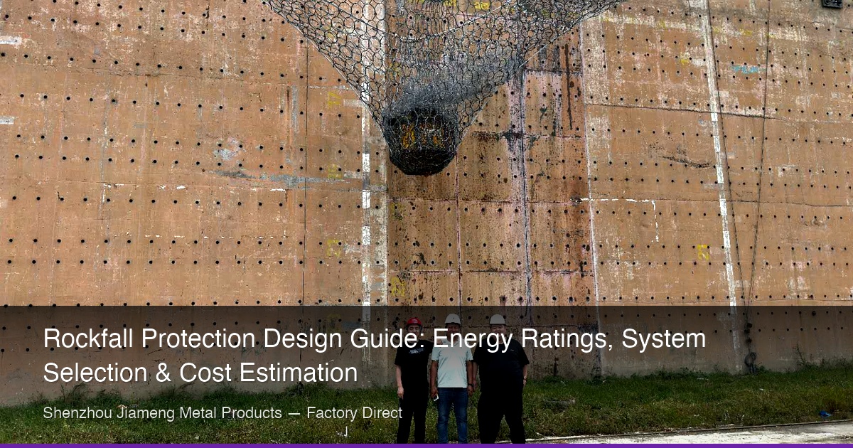
Rockfall protection design is an engineering discipline that balances geotechnical assessment, energy absorption calculations, and system configuration to create effective barriers against falling rock and debris. Whether you are designing for a mountain highway, a mining operation, or a railway corridor, understanding energy ratings, system types, and site-specific parameters is essential for selecting the right protection system. This guide covers the complete design workflow from hazard assessment through system selection and cost estimation.
🔑 Key Takeaways
- 🔹 Energy rating (kJ) is the #1 design parameter — always base system selection on trajectory analysis, never guess: a 1,000 kg boulder at 20 m/s carries 200 kJ of kinetic energy
- 🔹 ETAG 027 certification is non-negotiable for critical infrastructure: only full-scale crash-tested barriers with valid ETA documents provide verifiable protection
- 🔹 Active systems prevent rockfall at the source (securing rock on the slope face); passive systems catch it after detachment — most major projects use both in combination
- 🔹 Brake elements are single-use energy absorbers: any barrier that has been impacted must have its brake elements inspected and replaced if any deformation is visible
- 🔹 Proper site investigation — including LiDAR survey, joint analysis, and anchor pull-out testing — prevents the most common causes of system failure: undersized foundations and underestimated block energy
📋 Table of Contents
- 1. Understanding Energy Ratings: The Foundation of Rockfall Protection Design
- 2. Active vs. Passive Systems: Choosing the Right Protection Philosophy
- 3. Rockfall Hazard Assessment: The Design Workflow
- 4. Barrier System Types: Ring Nets, Wire Rope, and Hybrid Configurations
- 5. Site Investigation: Key Parameters for Design
- 6. Installation and Construction Considerations
- 7. Cost Factors and Budgeting for Rockfall Protection
- 8. Standards and Certifications: What to Require
- 9. Maintenance and Inspection: Ensuring Long-Term Performance
- 10. Design Case Studies: Learning from Real Projects
1. Understanding Energy Ratings: The Foundation of Rockfall Protection Design
Every rockfall protection system is rated by its Maximum Energy Level (MEL) — the kinetic energy it can absorb during a rock impact, measured in kilojoules (kJ). This is the single most important parameter in system selection, because underestimating the required energy rating leads to catastrophic barrier failure, while overestimating it wastes money on unnecessarily heavy systems.
Kinetic energy of a falling rock is calculated as: E = ½mv², where m is the rock mass (kg) and v is the impact velocity (m/s). A 1,000 kg boulder falling at 20 m/s carries 200 kJ of kinetic energy — enough to destroy an inadequately rated barrier.
| Energy Rating (kJ) | Typical Application | Max. Boulder Size (kg) | System Type |
|---|---|---|---|
| 100–250 | Small rockfall, soil slope erosion control | 50–250 | Simple drape mesh / light ring nets |
| 500 | Moderate rockfall on secondary roads | 250–750 | Standard ring net barrier |
| 1,000 | High-traffic highways, railway corridors | 750–1,500 | Heavy ring net / wire rope barrier |
| 2,000 | Critical infrastructure, mining haul roads | 1,500–3,000 | High-energy ring net with brake elements |
| 3,000–5,000 | Major rockfall on strategic infrastructure | 3,000–8,000 | Multi-layer systems / engineered rockfall galleries |
| 5,000–8,500 | Extreme conditions, avalanche/rockfall combined zones | 8,000+ | Specialized high-capacity systems |
Modern rockfall barriers are tested and certified according to ETAG 027 (European Technical Approval Guideline) or the Swiss Guideline FOEN/BFU. Certification requires full-scale impact testing at the rated MEL, with the barrier retaining the impacting block within a defined residual height. Always specify ETAG 027-certified systems for critical infrastructure — uncertified products carry unquantified risk.
2. Active vs. Passive Systems: Choosing the Right Protection Philosophy
Rockfall protection systems fall into two fundamental categories based on their intervention point in the rockfall process:
Active Systems prevent rockfall from initiating by securing unstable rock masses and loose debris on the slope face. They work at the source, eliminating the hazard rather than catching falling rock. Active systems include high-tensile steel wire mesh (TECCO® type) tensioned and anchored to the slope face, wire rope netting for larger block sizes, and soil nailing with shotcrete for highly fractured rock masses.
Passive Systems intercept falling rock after detachment, absorbing its kinetic energy through deformation of structural components. These systems do not prevent rockfall — they catch it. Passive systems include rockfall catch fences with flexible ring nets or wire rope barriers, rockfall embankments built at the slope base, and reinforced concrete rock sheds covering vulnerable infrastructure.
| Comparison Factor | Active Systems | Passive Systems |
|---|---|---|
| Where installed | On the slope face (source zone) | At the slope toe or on benches |
| How it works | Prevents rock from detaching | Catches rock after it falls |
| Maintenance requirement | Low — once installed, minimal maintenance | Medium — clearance of accumulated debris needed |
| Visual impact | Low to moderate — mesh blends with slope | Higher — visible barriers at slope base |
| Cost (relative) | $$–$$$ (requires rope access installation) | $$–$$$$ (depends on energy rating) |
3. Rockfall Hazard Assessment: The Design Workflow
A rigorous rockfall hazard assessment follows a structured four-step workflow:
Step 1: Geological mapping and rock mass characterization. Identify joint sets, bedding planes, and fracture patterns. Measure joint orientations (dip/dip direction) using compass-clinometer. Assess rock mass quality using RMR (Rock Mass Rating) or GSI (Geological Strength Index). Document block sizes and shapes of potentially unstable rock masses.
Step 2: Trajectory analysis. Use 2D or 3D rockfall simulation software (RocFall, CRSP, Rockyfor3D). Input: slope geometry from LiDAR or photogrammetry survey, slope material properties (restitution coefficients), and block characteristics (mass, shape, initial position). Output: bounce height envelopes, kinetic energy distribution, runout distance, and impact velocity at barrier locations.
Step 3: Risk quantification. Calculate annual probability of rockfall events reaching the infrastructure. Assess consequences: potential casualties, economic loss, service disruption. Classify risk level per national guidelines (e.g., UK Highways Agency HD 22/08, Swiss FOEN guidelines). Determine acceptable risk threshold and required protection level.
Step 4: System selection and design. Match energy requirements to certified system ratings. Consider barrier height: must exceed maximum bounce height plus safety margin (typically +1.5m). Determine barrier length and post spacing based on slope geometry. Select anchoring type based on foundation conditions.
4. Barrier System Types: Ring Nets, Wire Rope, and Hybrid Configurations
Modern rockfall barriers use several distinct energy-absorbing technologies, often combined in hybrid configurations for extreme applications.
| Barrier Type | Typical Energy Range (kJ) | Max. Post Spacing (m) | Best For |
|---|---|---|---|
| Simple drape mesh (single/double twist) | 50–250 | 3–5 | Small rockfall, soil erosion, secondary slopes |
| Ring net barrier (standard) | 500–2,000 | 8–10 | Highways, mountain roads, general infrastructure |
| Ring net barrier (high-energy) | 2,000–5,000 | 10 | Mining, critical infrastructure, major highways |
| Wire rope barrier with brake rings | 3,000–8,500 | 10 | Extreme rockfall, avalanche combined zones |
| Hybrid system (ring net + wire rope layers) | 5,000–8,500 | 10 | Largest expected rockfall events |
Brake elements are the heart of modern high-energy barriers. These deformable steel rings or tubes are integrated into the supporting ropes and absorb energy through plastic deformation during impact. A single barrier may have 4-8 brake elements, each capable of absorbing 50-150 kJ. The brake elements are the primary reason modern barriers can handle 5,000+ kJ impacts while remaining lightweight and relatively easy to install.
5. Site Investigation: Key Parameters for Design
Inadequate site investigation is the most common cause of rockfall protection system failure. Before specifying any system, these parameters must be quantified:
- Slope geometry: Height, angle, profile (convex/concave/stepped), and bench locations. A LiDAR or drone photogrammetry survey is ideal.
- Geology and rock mass: Rock type, strength (UCS), weathering grade, joint spacing and persistence, block size distribution. Rock mass classification: RMR > 50 is generally stable; RMR < 30 requires active stabilization.
- Ground conditions for anchoring: Soil/rock type at post foundation locations, bearing capacity, groundwater conditions. Post foundations must resist overturning moments from barrier impact.
- Design block: The 95th percentile block size expected from the slope, determined from joint spacing analysis and field observation of fallen blocks.
- Impact velocity: Typically 15-30 m/s for steep slopes (>45°), 10-20 m/s for moderate slopes. Higher velocities dramatically increase kinetic energy (quadratic relationship).
- Access and constructability: Can equipment reach the site? Is rope access required? Does the slope face require scaling (removal of loose rock) before installation?
6. Installation and Construction Considerations
Proper installation is as critical as proper design. Slope preparation begins with scaling loose rock from the face — dangerous work requiring qualified rope access technicians. Active mesh systems require systematic anchoring, typically 3-5 anchors per 100 m² depending on slope condition. Anchor type (grouted rebar, self-drilling, expansion shell) is selected based on rock quality. Pull-out testing of representative anchors is mandatory (minimum 5 tests per anchor type).
Passive barrier posts transfer enormous overturning moments to the ground during impact. Foundations must be designed by a geotechnical engineer considering soil/rock strength and expected impact loads. In competent rock, rock bolts with base plates may suffice; in soil, reinforced concrete footings are required. For active mesh systems, proper tensioning of the mesh is essential — hydraulic tensioning tools should achieve specified pretension of 10-20 kN per anchor point. Barrier ropes must be pre-tensioned to eliminate slack before brake elements activate during impact.
7. Cost Factors and Budgeting for Rockfall Protection
Rockfall protection costs vary enormously based on system type, site accessibility, and required energy rating. Indicative installed cost ranges (2024 prices, excluding mobilization):
| System Type | Installed Cost (USD/m²) | Key Cost Drivers |
|---|---|---|
| Active drape mesh (simple) | $25–45 | Slope accessibility, anchor drilling difficulty |
| Active TECCO® type (high-tensile) | $45–80 | Mesh cost (wire strength), anchor density |
| Passive barrier (500–1,000 kJ) | $500–1,200 / lin.m | Barrier height, energy rating, foundation conditions |
| Passive barrier (2,000–3,000 kJ) | $1,200–2,500 / lin.m | Brake ring count, post size, foundation complexity |
| Passive barrier (5,000+ kJ) | $2,500–5,000+ / lin.m | Specialized design, large foundations, crane access |
Cost composition (typical passive barrier project): Materials (mesh, ropes, posts, brake elements): 35-45%; Foundations and anchoring: 15-25%; Installation labor: 20-30%; Mobilization, access equipment, engineering: 10-20%. Sourcing materials directly from manufacturers in China can reduce material costs by 30-50% compared to European suppliers, provided the products are ETAG 027 certified.
8. Standards and Certifications: What to Require
Rockfall protection systems for critical infrastructure must comply with recognized standards. ETAG 027 (EAD 340059-00-0106) is the European guideline for flexible rockfall protection kits, requiring full-scale crash testing at the rated MEL. Certified systems receive a European Technical Assessment (ETA). ONR 24810 (Austrian) provides complementary design methodology and maintenance requirements. The Swiss FOEN Guidelines cover hazard mapping and risk assessment. ISO 17746 (under development) aims to harmonize international requirements.
Critical procurement requirement: For any project requiring insurance coverage or regulatory approval, specify ETAG 027-certified systems. Accept nothing less than a valid ETA document from the system manufacturer. Uncertified products represent unquantifiable risk — if a barrier fails during a rockfall event, the legal liability can fall on the designer, contractor, or project owner. Wire rope standards (EN 12385, EN 10264) and corrosion protection standards (EN ISO 1461 for HDG, EN 10244-2 for Zn-Al) apply to all steel components.
9. Maintenance and Inspection: Ensuring Long-Term Performance
Rockfall protection systems are not "install and forget." After every major storm or rockfall event, perform visual inspection for damage, debris accumulation, and barrier deformation. Annual inspections should include corrosion assessment, tension checks on active mesh anchors, and brake element deformation check — replace any activated elements immediately. Every 5 years, conduct comprehensive engineering inspection with pull-out testing of representative anchors, coating thickness measurement, and structural integrity assessment.
Key maintenance actions include debris clearance from behind passive barriers (a full barrier has reduced capacity), brake element replacement (they are one-time-use energy absorbers), corrosion treatment with zinc-rich paint on damaged galvanizing, mesh repair or replacement, and vegetation control to prevent trees from falling onto barriers or compromising anchor points through root growth.
10. Design Case Studies: Learning from Real Projects
Case 1: Highway Rockfall Protection, Sichuan, China (2019). A 1.2 km mountain highway section experienced frequent rockfall events blocking traffic 3-5 times per year. Trajectory analysis determined design block size of 2,500 kg with impact energy up to 1,800 kJ. Solution: 8,200 kJ-rated ring net barriers (10 posts, 7m height) at 8 critical locations. Total installed cost: $1.8 million. Result: Zero rockfall incidents reaching the highway in 5 years.
Case 2: Open-Pit Mine Slope Stabilization, Chile (2020). A copper mine required stabilization of a 150m-high bench with fractured andesite (RMR = 35). Solution: Active TECCO® type G65 high-tensile mesh over 25,000 m², with 5,800 systematic rock bolts (4m length, grouted). Rope access installation. Total cost: $2.1 million. Result: Zero displacement after 3 years, allowing safe mining operations beneath the stabilized zone.
Case 3: Railway Corridor Protection, Switzerland (2021). A 300m section below an unstable limestone cliff required protection against design blocks up to 5,000 kg (impact energy 3,200 kJ). Solution: Hybrid barrier with 3 layers of ring nets and 12 brake elements per 10m section, achieving 8,500 kJ total rated capacity. Helicopter-assisted installation. Total cost: CHF 4.2 million. Result: System intercepted 3 significant rockfall events in first year, preventing service disruption on a line carrying 200 trains/day.
Need Slope Protection Systems? Contact Us Now
Active and passive rockfall protection netting, ring nets, and wire rope mesh. Engineered to 3000kJ energy absorption. Third-party test reports included. Factory-direct pricing — get your quote in 24 hours.