Active Slope Protection Netting: Standards, Installation, and Performance Testing

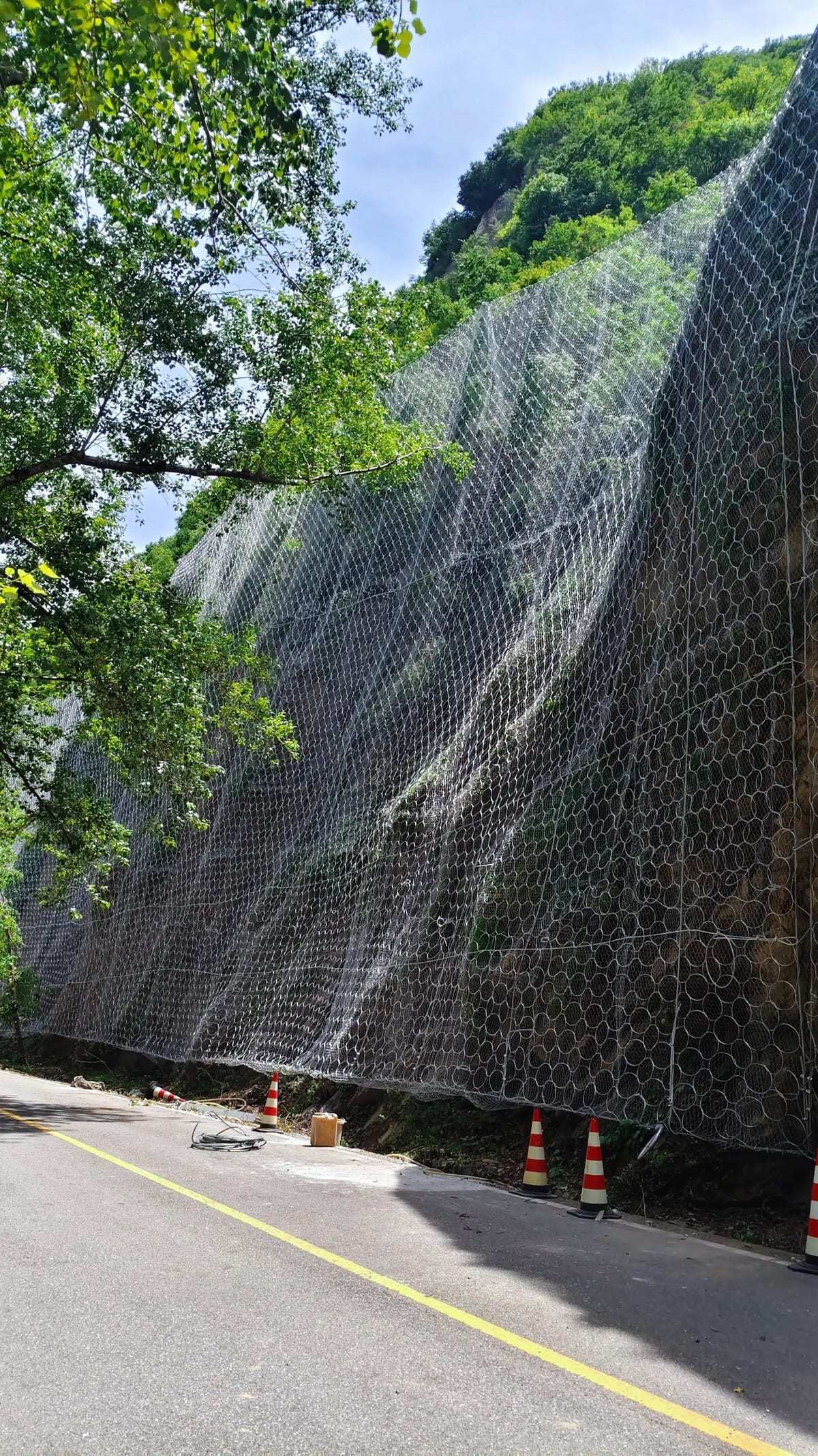
Active slope protection netting represents a proactive approach to slope stabilization — preventing rockfalls and landslides before they occur rather than simply catching debris after it falls. Unlike passive systems that wait for failure, active systems work continuously to maintain slope integrity by securing loose rock formations and surface materials in place. This makes them the preferred solution for highways, railways, and infrastructure projects where even a single rockfall event could have catastrophic consequences.
📋 Table of Contents
- 1. Design Principles of Active Slope Protection
- 2. High-Tensile Steel Wire Mesh Specifications
- 3. Anchoring Systems and Spike Plates
- 4. Boundary Ropes and Edge Reinforcement
- 5. Installation Process Step by Step
- 6. Performance Testing and Verification
- 7. Monitoring and Long-Term Maintenance
- 8. Integration with Other Slope Protection Measures
This article explores active slope protection netting systems in depth, covering design principles, material standards, installation techniques, and how to integrate active systems into comprehensive slope management strategies.
1. Design Principles of Active Slope Protection
Active slope protection systems work on a fundamental engineering principle: confinement. By applying a continuous restraining force across the slope surface, the mesh system prevents individual rocks and soil particles from dislodging, even as weathering and environmental factors gradually weaken the slope material.
The design process begins with a thorough geotechnical investigation. Engineers assess rock mass quality using classification systems like RMR (Rock Mass Rating) or GSI (Geological Strength Index). Slope geometry — height, angle, and profile — determines the mesh coverage pattern and anchor placement strategy.
Critical design parameters include the required mesh tensile strength, anchor pull-out capacity, and plate dimensions for spike plates that distribute the restraining force across the mesh surface. For slopes with highly fractured rock, additional surface treatments such as shotcrete or erosion control mats may be integrated with the mesh system.
2. High-Tensile Steel Wire Mesh Specifications
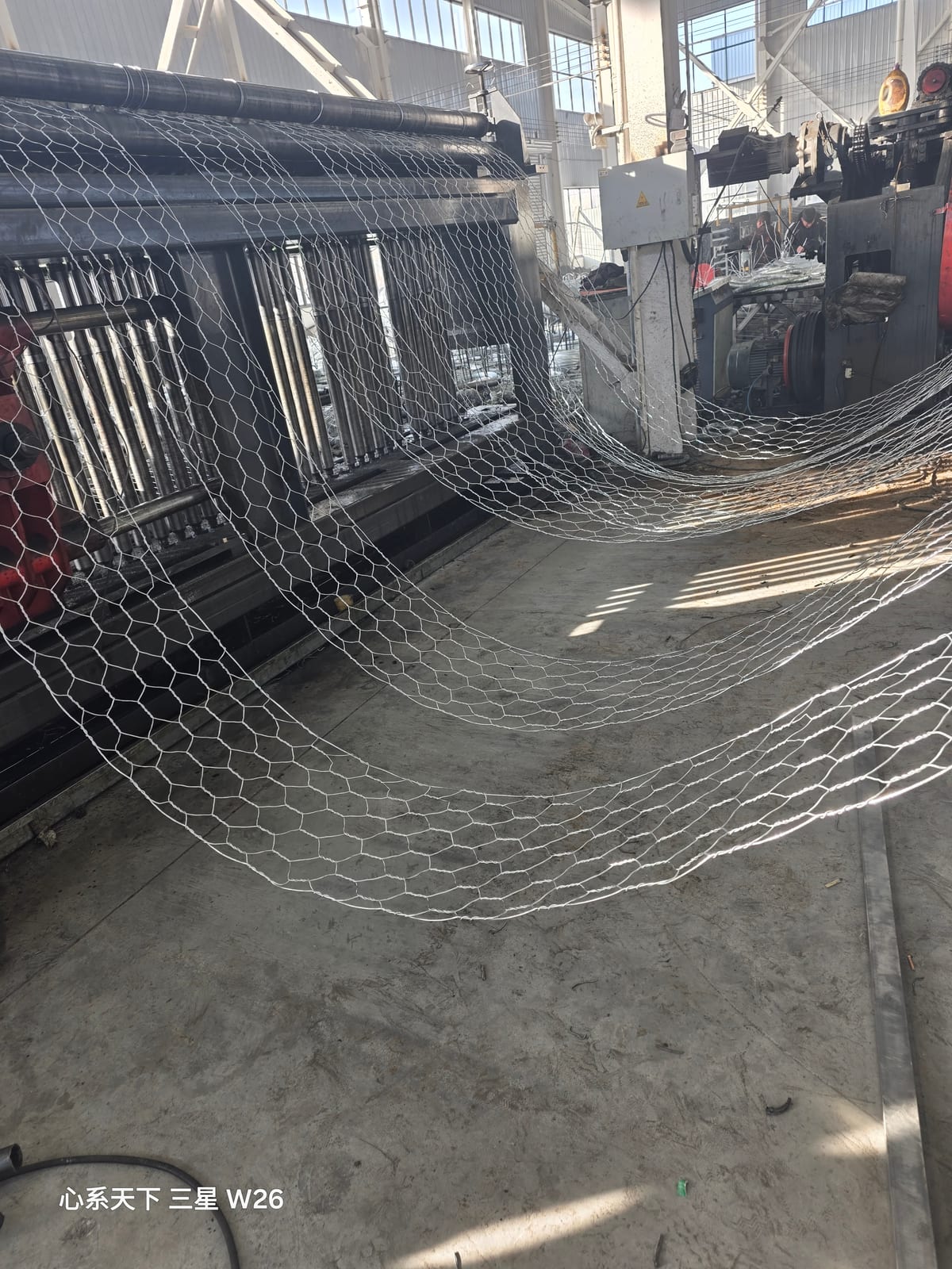
The core component of any active slope protection system is the high-tensile steel wire mesh. This is not ordinary wire mesh — it is specifically engineered for slope stabilization applications with significantly higher strength requirements than general-purpose mesh products.
Tensile Strength: Active slope mesh wire must have a minimum tensile strength of 1,770 N/mm². This is approximately 3-4 times stronger than standard gabion mesh wire (380-550 N/mm²). The high tensile strength allows thinner wire diameters to achieve the required system strength while minimizing weight and material cost.
Wire Diameter: Common wire diameters for active slope mesh range from 2.0mm to 4.0mm, with 3.0mm being the most widely specified. Thicker wire provides greater puncture resistance against sharp rock edges but adds weight and cost.
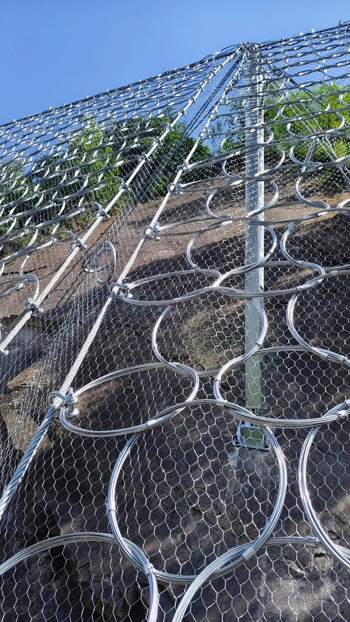
Mesh Opening Size: TECCO-style diamond mesh typically uses 83×143mm openings, providing an optimal balance between rock retention capability and material efficiency. Smaller openings may be specified for slopes with smaller loose material.
Coating: Super-galvanized coating (Zn-5%Al or Galfan) with minimum 150 g/m² coating weight is standard. For highly corrosive environments, specify Zn-10%Al coating or stainless steel wire.
3. Anchoring Systems and Spike Plates
The mesh alone cannot stabilize a slope — it must be securely anchored to competent rock or soil. The anchoring system transfers the restraining force from the mesh into the slope mass.
Soil Nails: For soil slopes and highly weathered rock, soil nails (typically 25-32mm diameter steel bars) are grouted into drilled holes at depths of 3-8 meters. The nail head includes a bearing plate and nut that secures the spike plate against the mesh.
Rock Bolts: For competent rock slopes, rock bolts provide higher pull-out capacity. Self-drilling anchor bolts are increasingly popular as they combine drilling and grouting in a single operation, reducing installation time on difficult access slopes.
Spike Plates: These specialized plates distribute the anchor force across the mesh surface. Standard spike plates are 300×300mm with pressed ribs that grip the mesh wires. For very weak rock, larger plates (400×400mm or custom sizes) provide a larger bearing area.
Anchor Spacing: Typical anchor spacing is 2.0m to 3.0m center-to-center, arranged in a regular grid pattern. Closer spacing is used in highly fractured zones or where higher system stiffness is required. Each anchor must be individually designed based on the expected load contribution from its tributary area.
4. Boundary Ropes and Edge Reinforcement
The perimeter of an active slope mesh system requires special reinforcement to prevent progressive failure starting from the edges. Boundary ropes — typically 12-16mm diameter steel wire ropes — are installed along the top, bottom, and side boundaries of the meshed area.
The top boundary rope is particularly critical. It anchors the upper edge of the mesh system and must be secured to a row of closely-spaced anchors (typically 1.5m spacing) along the slope crest. This prevents the mesh from peeling away from the slope surface under snow load, debris accumulation, or rockfall impact from above.
Side boundary ropes are installed where the mesh coverage area ends, providing a clean termination and preventing mesh unraveling. Compression-type rope clips or wire rope grips secure the mesh to the boundary ropes at regular intervals.
5. Installation Process Step by Step
Installing active slope protection netting requires specialized equipment and trained personnel. The process typically follows these steps:
Step 1 — Site Preparation: Remove loose rock, vegetation, and debris from the slope surface. Scaling (manual removal of unstable rock) should be performed from the top down using rope access techniques.
Step 2 — Anchor Drilling and Installation: Drill holes to the specified depth and diameter. Install soil nails or rock bolts with cement grout. Allow adequate curing time before tensioning (typically 3-7 days depending on grout type and temperature).
Step 3 — Mesh Deployment: Unroll mesh panels from the top of the slope downward. Panels are typically 3.5m wide and up to 30m long. Overlap adjacent panels by at least 200mm and interconnect using lacing wire or C-rings.
Step 4 — Spike Plate Installation: Position spike plates over each anchor point, ensuring the ribs engage the mesh wires. Tighten anchor nuts to the specified torque to achieve the design pre-tension.
Step 5 — Boundary Rope Installation: Install boundary ropes along the perimeter and secure with anchor points at specified intervals. Ensure ropes are properly tensioned to prevent sagging.
Step 6 — Quality Inspection: Verify anchor torque, mesh tension, overlap connections, and boundary rope security. Document the installation with photographs and pull-out test records for a sample of anchors.
6. Performance Testing and Verification
Active slope protection systems should be validated through both laboratory and field testing:
Mesh Tensile Testing: Wire samples are tested to verify tensile strength meets the 1,770 N/mm² minimum specification. Testing follows ISO 6892-1 procedures.
Punch Test: A standardized punch test (following EN 10223-3 or equivalent) verifies the mesh's resistance to puncture by a 50mm diameter steel cone. This simulates the action of a sharp rock pressing against the mesh.
Anchor Pull-Out Testing: A representative sample of installed anchors (typically 5% with a minimum of 3) is tested to verify pull-out capacity meets or exceeds the design value. Testing uses hydraulic jacks with calibrated load cells.
Full-Scale Field Testing: For critical projects, a full-scale test section may be constructed and monitored under actual environmental conditions for 6-12 months before proceeding with the complete installation.
7. Monitoring and Long-Term Maintenance
Active slope protection systems require ongoing monitoring to ensure continued performance:
Visual Inspections: Conduct quarterly visual inspections to check for mesh sagging, loose anchors, corrosion, debris accumulation, and vegetation overgrowth. Pay special attention to areas where water seepage is visible, as this may indicate drainage issues behind the mesh.
Anchor Re-Tensioning: Some anchor relaxation over time is normal. Annual spot-checks of anchor torque on a random sample verify that pre-tension remains within acceptable limits. Re-tension as needed.
Corrosion Monitoring: In aggressive environments, use coating thickness gauges to measure remaining zinc/aluminum coating thickness at representative locations. Plan for mesh replacement when coating thickness drops below 50% of the original specification.
Instrumentation: For high-risk slopes, consider installing inclinometers, extensometers, or load cells on selected anchors to provide continuous monitoring data. Automated alert systems can trigger inspections when pre-set thresholds are exceeded.
8. Integration with Other Slope Protection Measures
Active mesh systems rarely work in isolation. They are most effective when integrated with complementary slope protection measures:
Surface Drainage: Install drainage ditches at the slope crest to intercept surface runoff before it reaches the meshed area. Within the mesh area, drainage pipes or weep holes prevent water pressure buildup behind the mesh.
Deep Drainage: Horizontal drain holes drilled into the slope relieve groundwater pressure, a common cause of slope instability. These should be installed before mesh deployment to avoid damage to the mesh system.
Vegetation: Hydroseeding or planting through the mesh establishes vegetation that provides long-term reinforcement through root systems. The mesh protects young plants from erosion while they establish.
Passive Barriers: For slopes where active systems cannot achieve 100% reliability (e.g., areas with large detached blocks), passive rockfall barriers at the slope toe provide a secondary line of defense.
Secure Your Slope — Get a Custom Protection Plan
Describe your slope conditions — height, angle, rock type, and risk level. Our engineering team will design a tailored rockfall protection solution with detailed specifications and pricing.
📱 Get Slope Solution 📧 Send Email